
| Orig. Posting Date | User Name | Edit Date |
| Mar 26, 2024 11:13AM | MPlayle | |
| Mar 26, 2024 08:05AM | flopek | |
| Mar 26, 2024 05:43AM | MPlayle | |
| Mar 26, 2024 05:39AM | Alex | |
| Mar 25, 2024 10:00PM | flopek | |
| Mar 25, 2024 04:02PM | Kermy | |
| Mar 25, 2024 03:14PM | flopek | |
| Mar 25, 2024 02:22PM | MPlayle | |
| Mar 25, 2024 02:07PM | Dan Moffet | |
| Mar 25, 2024 12:54PM | flopek | Edited: Mar 26, 2024 07:56AM |
| Mar 25, 2024 07:14AM | Dan Moffet | |
| Mar 25, 2024 05:49AM | ve9aa | |
| Mar 25, 2024 02:59AM | Dan Moffet | Edited: Mar 25, 2024 07:20AM |
| Mar 24, 2024 07:45PM | flopek |

|
Total posts: 1787
Last post: Mar 26, 2024 Member since:Feb 1, 2000
|
Cars in Garage: 0
Photos: 0 WorkBench Posts: 0 |
|
|
|
Total posts: 5
Last post: Mar 26, 2024 Member since:Jul 7, 2021
|
Cars in Garage: 0
Photos: 0 WorkBench Posts: 0 |
|
|
Total posts: 1787
Last post: Mar 26, 2024 Member since:Feb 1, 2000
|
Cars in Garage: 0
Photos: 0 WorkBench Posts: 0 |
|
|
|
Total posts: 10238
Last post: Apr 26, 2024 Member since:Mar 24, 1999
|
Cars in Garage: 0
Photos: 0 WorkBench Posts: 0 |
|
|
|
Total posts: 5
Last post: Mar 26, 2024 Member since:Jul 7, 2021
|
Cars in Garage: 0
Photos: 0 WorkBench Posts: 0 |
I did some research on this after getting more pieces of the puzzle and found this forum that explains some of this as well.
https://www.theminiforum.co.uk/forums/topic/275373-charcoal-canister-connecting/
|
|
Total posts: 333
Last post: Apr 13, 2024 Member since:Jan 22, 2018
|
Cars in Garage: 0
Photos: 0 WorkBench Posts: 0 |
|
|
Total posts: 5
Last post: Mar 26, 2024 Member since:Jul 7, 2021
|
Cars in Garage: 0
Photos: 0 WorkBench Posts: 0 |
Ok, thanks for the diagram, but it looks like the mystery deepens because that exact canister is nowhere to be found in my car. I experimented a little and bypassed the switch and the electronic gizmo on firewall and ran the vacuum line from the manifold to the actuator disk on the carb, and it seemed to like that, but it did idle about 200-300 rpms higher than I would like, but it was like an open vac but without the sucking sound I get with the switch when it clicks to open.
I've concluded then I have a hacked setup based on the comments about the dual carb and all. I'm fairly new to the ins-and-outs of classic minis.
Any recommendations and advice for my situation would be welcomed for consideration. I don't know if I want to start adding emissions parts to this system that would complicate the simplicity, or the fact it's currently not required in my state to pass any emissions tests (it's licensed as a collector vehicle, and exempt).
|
|
Total posts: 1787
Last post: Mar 26, 2024 Member since:Feb 1, 2000
|
Cars in Garage: 0
Photos: 0 WorkBench Posts: 0 |
|
https://www.minispares.com/catalogues/classic/Classic~Mechanical~Parts~Manual/Engine/Engine~Breathers~.aspx?2~12~117
The diagram has a boxed off section in the lower right that shows the thermo switch and the line from it to the charcoal cannister.
|
|
Total posts: 9547
Last post: Apr 26, 2024 Member since:Aug 14, 2002
|
Cars in Garage: 0
Photos: 0 WorkBench Posts: 0 |
|
It appears your distributor vacuum advance is connected directly to the carb port separately, which seems OK to me (throwing my wild guess out!).
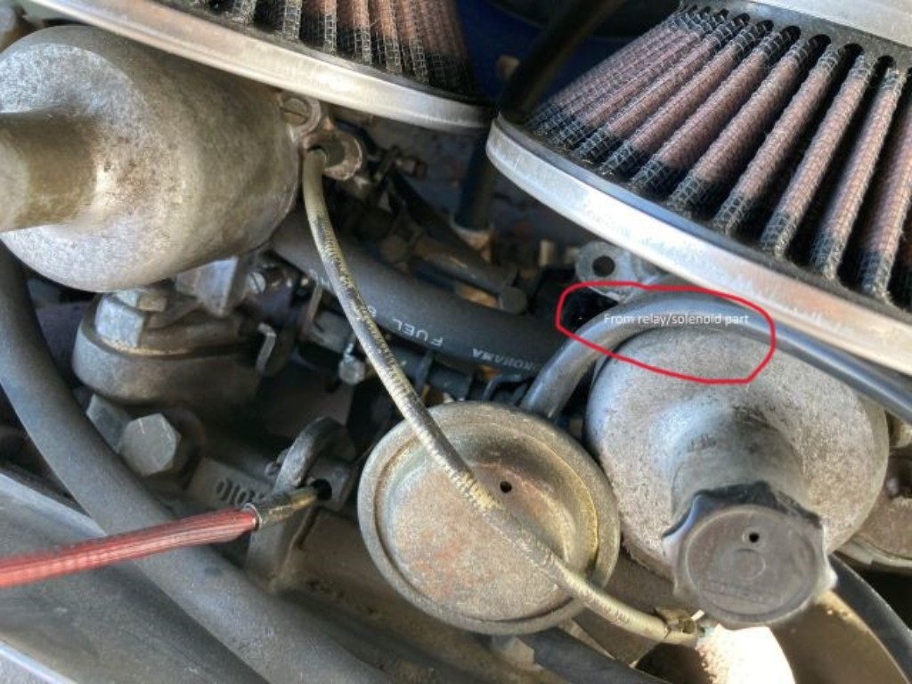
Dual carbs definitely seem non-standard! The other collection of vacuum lines draw from the intake manifold port and eventually connect to the round gizmo beside the carb, which appears to be a positive crankcase ventilation valve. No idea what the actuator on the firewall does - maybe tracing the wire colours in a wiring diagram might tell you what it does. Maybe it is an electrically controlled vacuum valve managed by the ignition switch??
I am wondering if in the original configuration the system used the open port to control the distributor vacuum advance and when the twin carbs were added, the carb port was used for the dizzy.
.
"Hang on a minute lads....I've got a great idea."
|
|
Total posts: 5
Last post: Mar 26, 2024 Member since:Jul 7, 2021
|
Cars in Garage: 0
Photos: 0 WorkBench Posts: 0 |
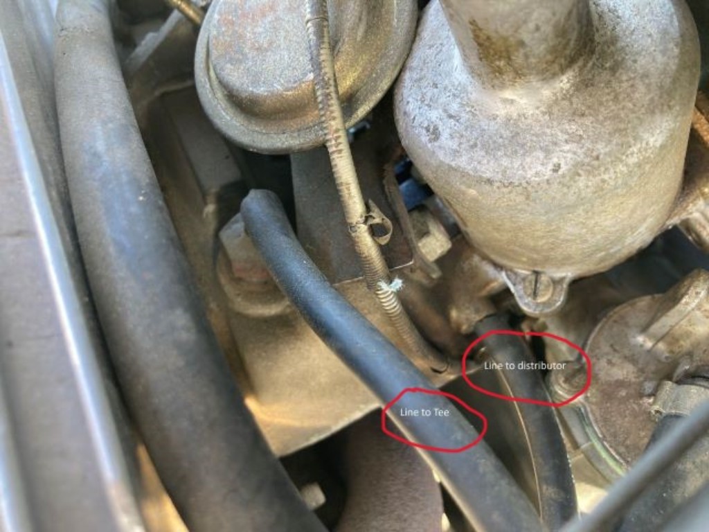
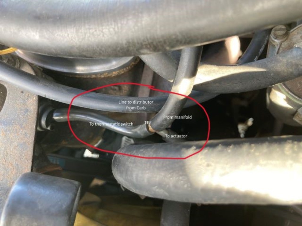
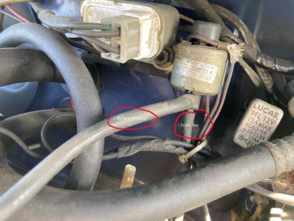
Thank you for the replies. I do suspect some previous hacking and/or transplant and suspect that the open switch port was a hack to get it to run better since the open vacuum makes it idle fine. I am wondering if it is even needed, but plugging it causes very rough idling. I just don't like the idea of something switching from time to time and also sucking in straight air. I attached some pictures and there is a Tee in the vacuum lines to the switch from the manifold that ultimately go to the carb actuator.
As for the vacuum from the carb to the distributor, that is there and a totally different dedicated line.
|
|
Total posts: 9547
Last post: Apr 26, 2024 Member since:Aug 14, 2002
|
Cars in Garage: 0
Photos: 0 WorkBench Posts: 0 |
|
My other guess is that flopek's car has received a transplant.
.
"Hang on a minute lads....I've got a great idea."
|
|
Total posts: 8592
Last post: Apr 6, 2024 Member since:Sep 30, 2002
|
Cars in Garage: 4
Photos: 40 WorkBench Posts: 2 |
|
Assuming by your post that one leg is connected to the carb or intake manifold, my guess is that the other leg would be connected to the vacuum advance of a distributor. My theory is that when the engine is cold, the valve is closed, preventing vacuum advance from occurring to allow easier starting. Once it opens, vacuum advance is permitted but since the system is closed, there is no air leak.
If this is the case, It should run fine once connected.
Depending on your engine and distributor, the specs may require you to disconnect the vacuum advance when tuning the engine. IF so, you would have to disconnect one of the lines and plug it for the work.
I was wondering what this switch was, as I have an 87 Mini City-E (not far from your 85 Mayfair) so something is "off".
From the link you quoted:
"...Fitted to 1275cc carb type engines from 1992 to 1994. Has 2 vacuum pipes conected to it. Screws into thermostat housing under top radiator hose. Use with special washer MAW10001...."
~ 30 minutes in a Mini is more therapeutic than 3 sessions @ the shrink. ~
Mike ![]() NB, Canada
NB, Canada
|
|
Total posts: 9547
Last post: Apr 26, 2024 Member since:Aug 14, 2002
|
Cars in Garage: 0
Photos: 0 WorkBench Posts: 0 |
|
Assuming by your post that one leg is connected to the carb or intake manifold, my guess is that the other leg would be connected to the vacuum advance of a distributor. My theory is that when the engine is cold, the valve is closed, preventing vacuum advance from occurring to allow easier starting. Once it opens, vacuum advance is permitted but since the system is closed, there is no air leak.
If this is the case, It should run fine once connected.
If your engine does not have a distributor with vacuum advance, you could plug the line going to the carb. Vacuum advance generally works to provide earlier spark at idle or part throttle to allow leaner carb settings during those events, to improve fuel economy in road cars. As soon as you open the throttle, vacuum reduces and the vac advance goes way to be replaced with mechanical advance inside the distributor.
Depending on your engine and distributor, the specs may require you to disconnect the vacuum advance when tuning the engine. IF so, you would have to disconnect one of the lines and plug it for the work.
.
"Hang on a minute lads....I've got a great idea."
|
|
Total posts: 5
Last post: Mar 26, 2024 Member since:Jul 7, 2021
|
Cars in Garage: 0
Photos: 0 WorkBench Posts: 0 |
Thank you,
Ian


